A Career in Technology
The following is a copy of the professional experience record prepared for the application to become a Chartered Member of the Institute of Mechanical Engineers during the late 1970's and 1980s.
Introduction
After completing my secondary school education in 1975, I joined EMI Electronics Ltd as a 1-3-1 Thick Sandwich mechanical engineering apprentice. The apprenticeship involved 6 months of workshop and management training prior to starting my studies at Cambridge University. During each of the university summer vacations I was attached to one of the company divisions for further practical experience. Since obtaining my degree in Engineering I have had three jobs. The first was for 6 months as a design engineer with EMI, the second was for three years as a test engineer with British Aerospace and my present job is with the European 0rganization for Nuclear Research as a design and project engineer. A brief outline of these jobs is given below.
June 1979 - December 1979
EMI Electronics Ltd, Radar and Equipment Division
Mechanical design engineer in the Stress 0ffice responsible for the mechanical design and development of radar and electronic equipment for military applications.
December 1979 - December 1983
British Aerospace PLC, Military Aircraft Division
Structural test engineer in the Mechanical Test Department responsible for fatigue testing military aircraft. The work included the preparation of initial proposals and budget estimates, the design, construction, commissioning and running of multi-channel computer-controlled fatigue test rigs.
January 1984 - May 1988
European Organization for Nuclear Research
Design and project engineer in the Mechanical Group of the Proton Synchrotron Division responsible projects involving the installation of mechanical and electrical equipment in particle accelerators. The work includes the technical liaison between physicists and specialist engineers to define the objectives, the preparation of engineering proposals, budgets and timelines for projects. ln addition responsible for supervising detail design, preparing technical specifications for manufacturing work and supervising installation work for projects.
EMI Electronics Ltd - Stress Office
The Stress Office at the Radar and Equipment Division was responsible for the engineering design and development of radar and electronic equipment for military purposes. During my 6 months with this office I worked on several small projects.
Electronic Warfare Training Pod
The design of an electronic warfare training pod was the first project worked on. This project involved the modification of existing Night Illumination System underwing pods for BAe Phantom aircraft so that they could be used for electronic warfare training. The existing equipment in the forward and aft bays (see Figure 2.1) were to be removed and replaced with electronic warfare equipment. No change in the mass, centre of gravity or moments of inertia of the modified pods was permitted so that it would not be necessary to carry out a new series of flight and jettison trials for the pods and thus keep costs to a minimum.


Figure - Night Illumination System pod layout for BAe Phantom aircraft
The electronic warfare equipment was arranged in a variety of possible configurations suggested by the electronic engineers. For each of these cases the centre of gravity and moments of inertia were calculated. ln addition it was also necessary to calculate the temperatures in the bays due to the thermal output of the electronic warfare equipment. If the temperatures were too high, then the heat exchanger was enlarged, and the calculations were repeated until a satisfactory configuration was obtained.
The cockpit control unit was stressed to ensure that it would survive the normal flight conditions without damage and to ensure that in the event of crash the unit would remain mounted and intact even though it were unserviceable. This problem required the use of a computer to calculate the centre of gravity of the unit together with manual calculations to check the unit integrity and mounting structure. AII calculations were submitted to the Airworthiness 0fficer for approval.
Inflatable radome for Royal Navy warships
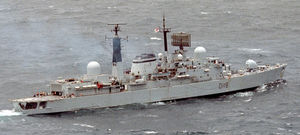
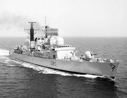
An inflatable radome was proposed by EMI as a replacement for existing rigid glass fibre designs mounted on Royal Navy destroyers. The radome was approximately 4 metres high and 2 metres diameter. The inflatable Kevlar radome was much lighter than existing units and permitted the replacement of damaged radomes while at sea.
It was my responsibility to calculate the inflation pressures required to keep the radome rigid during normal use (i.e. gale force winds) and in adverse conditions {i.e. blast effects}. It as also necessary to calculate the stresses in the floor structure of the radome and in the retaining clamps of the flexible envelope. The radome was normally inflated using electric fans but in adverse conditions was inflated to higher pressures by the ship’s pneumatic supply.
Inertial Navigation Unit
An Inertial Navigation Unit (lNU) was required to be mounted and aligned in the unpressurised bomb bay of a Canberra bomber trials aircraft. The commercially available Litton INU chosen was restricted to operation in pressurised aircraft or below a height of 6,000 feet. A container was therefore required to carry the INU together with an air conditioning unit (for cooling). The container was to be connected to the aircraft's cockpit pressurisation system.
The design of container eventually selected was an aluminium alloy box with pre-machined ribbed walls. This solution was the lightest of the possible alternatives which allowed the box to be reinforced around its mountings whilst material could be machined away to produce thin ribbed walls to support the internal pressure. A variety of pitches and depths of ribs were tried and the wall deflections and stresses calculated for each case. The optimum weight and stiffness of container was achieved using an iterative method.
The air conditioning system comprised of a fan and a heat exchanger mounted at one end of the box. The fan unit was designed to circulate sufficient air inside the container to cool the INU up to an altitude of 6,000 feet. The circulating air was cooled by the heat exchanger which had been designed to operate efficiently between the air inside the box and the ambient conditions in the bomb bay over the flight envelope of the aircraft.
A complete set of calculations verifying the strength of the container and its attachments to the aircraft for both the most extreme operating conditions and the crash case were submitted to the Airworthiness 0flicer for approval.
Vibration testing of electronic units for BAe Nimrod aircraft
Electronic units for radar equipment mounted in the Nimrod maritime reconnaissance were vibration tested prior to approval for mounting in the aircraft. It was my responsibility to design a structure (to simulate the units' aircraft mounting) for mounting on an electromagnetic vibrator. This work required the calculation of the strength and natural frequency of the structure in order that it would support the loads applied due the accelerations and as well as ensuring that its own natural frequency was high enough so that it would not affect the test results.
I was also required to witness the series of tests on the units. This was to confirm that they were carried out in accordance with the measured aircraft vibration spectrum in frequency and amplitude. ln addition this permitted the engineer to recommend modifications to the units to improve their mechanical design.


